BIM – Practical Approach to Level of Detail (LOD)
In this Digital Age, we see the construction industry working its way through Building Information Modeling (BIM) as the detail level can range from a broad geometric representation to creating an accurate as-built model. For a project to execute successfully everyone must speak the same language. Because the difference in understanding is going to cause problems. It is very important to have a better way of communicating the requirements between Project Owners, Designers, Contractors, etc., and that better way is known as the Level of Detail (LOD). LOD is a way where disciplines can communicate their requirements to one another.
In this article, we will understand the levels and how they can be used as a basis for contract documents and a medium (language) to communicate the needs and wants.
The Six Levels of Detail in Project
The American Institute of Architects (AIA) established LOD in the year 2008 when it has initially introduced five “levels of development” for defining the amount of detail about the BIM model. But later, to help the building trades adopt and implement them in a better way, BIMForum interpreted those levels for specific building components and published them in the year 2013 as Six Levels of Development (LOD).
These levels and features of building component and level of information at each LOD stage are described below:
LOD 100 (Concept)

This is a conceptual level, where the model element is graphically represented with generic shapes and symbols. The element in the model might just be a block representing the project. It does not entail any typical shape or size.
At this level, spaces of the project are modeled as generic objects with approx. sizes, shapes, and location. This level is to gain an understanding of the design and the spatial requirement. Blocks or space objects are placed in a model either in a random manner for quantification or in a blocking and stacking process.
Structural: Assumptions for structural elements are included such as architectural floor elements that contain a layer for assuming structural framing depth and other schematic elements that are not distinguishable by type of material.
MEPFP: It includes diagrammatic or schematic model elements where there is a conceptual/schematic layout or a flow diagram
LOD 200 (Approximate Geometry)
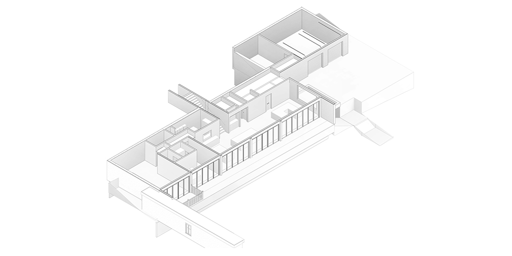
In this level, model elements are graphically represented within the model as a generic system, object, or assembly with approximate specifications, quantities, size, shape, location, and orientation. Any information derived from LOD 200 elements must be considered approximate. Non-graphic information may also be attached to the model element but it does not have any specific detail but it will present the geometry perfectly.
Structural: Approximate size, shape, the thickness of foundation, slab, etc, Also it includes a floor plan with approx. dimensions, approx. supporting framing members and structural grids are defined accurately.
MEP: Schematic layout including generic model elements with approx. size, shape, and location of all the MEP elements.
Fire Protection: It includes a schematic layout with approx. size, shape, and location of mains and risers and other equipment.
LOD 300 (Precise Geometry)
LOD 300 is similar to Construction Document (CD). It is a level where the model will contain accurate quantity, size, location, orientation, with detailing, fabrication, assembly, and installation information. Information contained by LOD 300 models can be used during the construction phase of the project.
Structural: All elements with the overall size, geometry, locations, and orientations of the structural element. It should include but not limit to defining material properties and finishes. Modeling should include sloping surfaces or floor depressions, main openings such as elevators or shafts, top, and size of pier, etc. External dimensions of the element should also be modeled.
MEPFP: Modeling of elements as per design-specified size, spacing, shape, and location of equipment/pipe/slope with given approximate allowances for spacing and clearance required for all specified anchors, supports, vibration, and seismic control that are utilized in the layout of the MEP equipment. Access/code clearance is required to model at LOD 300. For air distribution components, modeling of duct, dampers, fittings, insulation for risers, mains, and branches is required as per design-specified size, shape, spacing, and location of ducts.
LOD 350 (Precise Geometry with Connections)
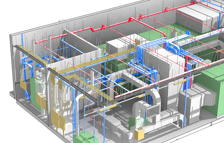
LOD 350 elements contain the same information as LOD 300, but they also include interfaces, supports, or connections with other building components. It displays how one system interacts with the other building systems.
LOD 400 (Fabrication)
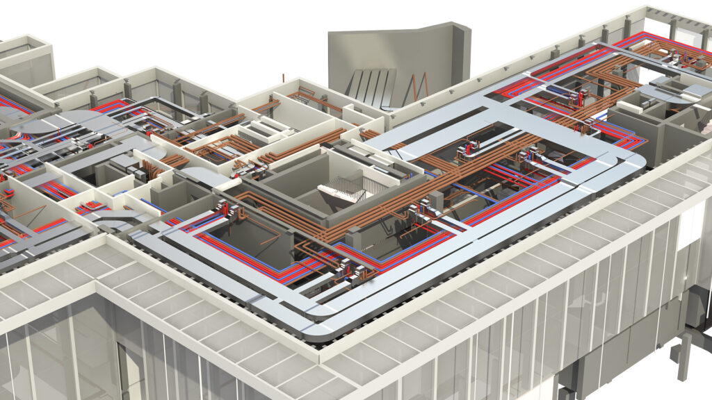
It is when complete fabrication and assembly information can be driven directly from the model. In other words, the details and information contained by LOD 400 elements can be handed over directly to suppliers to manufacture the building components being represented.
LOD 500 (As-built)
This level of the model will have all the suitable geometry and information to support operations and maintenance of the building lifecycle. They have been completed and installed and their location has been field-verified and they constrain information clients can be utilized post-construction like model number, manufactured, dates purchased, and so on.
For operations and maintenance of the facility and spatial management, following details are included in the model:
- Basic Information- system class, equipment name, developing BIM model of equipment, appearance description (word/picture), etc.
- Geometric Information- size, material, elevation, specific detail of the model (word/picture), etc.
- Maintenance Record- equipment resume, history records, checklist, record book of staff and schedule, etc.
- Equipment Detail Information- number, price, purchase date, specification, type, functions, unites, responsible person and units, brand/manufacture details, location, etc.
- Supplementary Information- warranty, assembly process, operation, manual, 2D manual, equipment performance table, manufacture information, etc.
Conclusion
LOD creates a standardized definition of what completion means and eliminates chances of discrepancies associated with project completion. Using LOD, teams working under different disciplines can communicate with each other in a better way with greater clarity. LOD enhances clarity in design by making use of advanced techniques and technology.